Introduction
Arduino IDE and associated microcontroller modules have taken the world by storm. It offers a programming environment that is so simple that it is being used school students for STEM education at the same time it offers sufficient capability that it can be used by professional for for quick implementation of control tasks.
With its open source philosophy, user base has grown phenomenally and has resulted in a very large number of libraries available in public domain. These libraries allow a user control from blinking of a LED to sophisticated quad-copter control.
In this series of articles, we will discuss the construction, operation, and basic programming of various components of the robot.
View of A Finished Robot
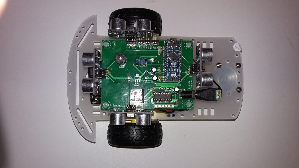
Robot Baseboard -The Brain
The robot is built around a baseboard that once populated serves as the brain of the robot. It supports:
- Arduino Nano or compatible module
- DIP socket to allow Arduino Nano or compatible board to be plugged in
- DIP socket to house Dual H-bridge motor driver IC SN754410
- Mounting for 4- ultrasonic sensors
- Socket to hold compass module – HMC5883L
- On-board buzzer
- DC- jack for power input 7.2 – 9V
- Screw terminals for motor interface
- Reverse battery polarity protection
- Ability to sense the low battery
- IIC and SPI extension interface connector
Controller Interface

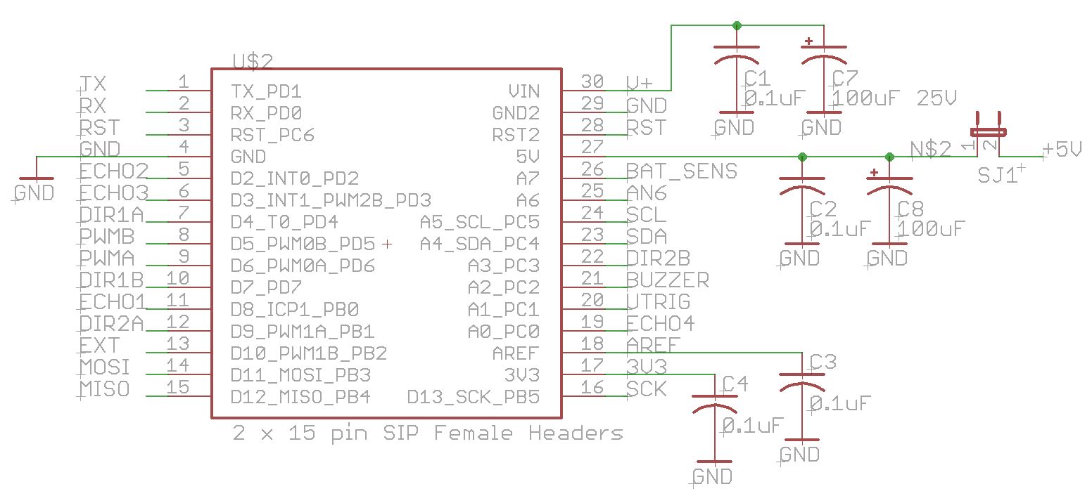
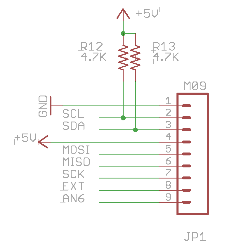
Expansion Interface
The expansion interface allows additional sensors and devices through IIC or SPI interface. It also feasible to even add another Arduino (or other) controller to add additional capability. One simple and useful interface is the IIC LCD that allows a 2×16 LCD screen to be added to display information.
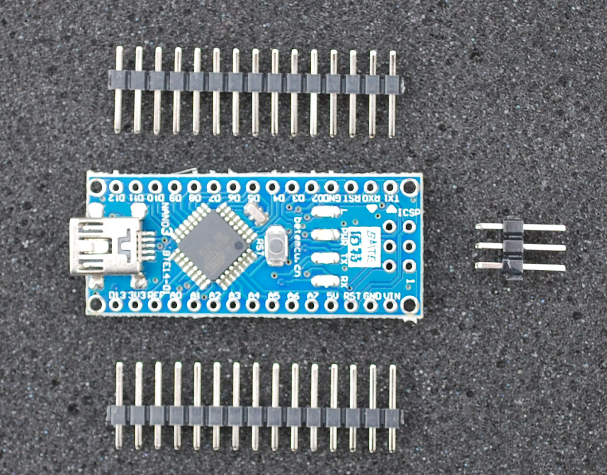
Arduino Nano Controller
The original Arduino Nano controller comes with pre-soldered pins and offers the most reliable option.
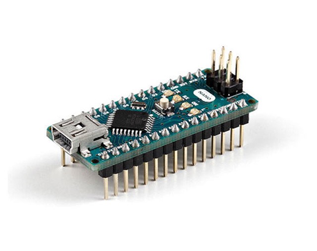
(click on the image to go to Arduino Store)
It can be ordered from the Arduino Store and other distributors. Even though, it costs more that the clone/compatible units, it is well constructed and offer greater reliability.
Arduino Nano Compatible Controller
Clones of Arduino Nano modules are widely available and are priced significantly lower than the original. The flip side of lower cost are two folds:
- Unsoldered pins (generally)
- Slight reliability issue with some vendors.

Amazon.com is a good place to start when looking for the compatible modules.
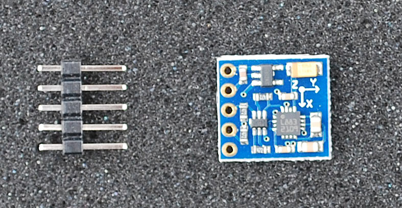
Compass Module
A compass module is a necessity, if the robot has to have a sense of direction. The baseboard has a 5-pin header that allows a common compass module HMC5883L to be mounted in a horizontal plane. The module again comes with pins that require soldering.
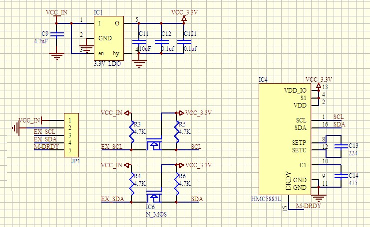
5 V to 3.3 V Interface
HMC5883L IC that is the heart of the compass module operates at 3.3 V. Furthermore, the HMC5883L IC communicates with Arduino, using IIC interface. In order to establish proper IIC communication without causing any issue to either of the two devices, 3.3 V to 5 V voltage translator interface is essential. Thie compass module contains all essential interface circuitry as well as a 5V to 3.3 V voltage regulator to power the HMC5883L IC.

Click to see the larger image of compass schematic
With the compass on board, Robot controller can determine the direction of travel (Magnetic north or south) in a horizontal plane.
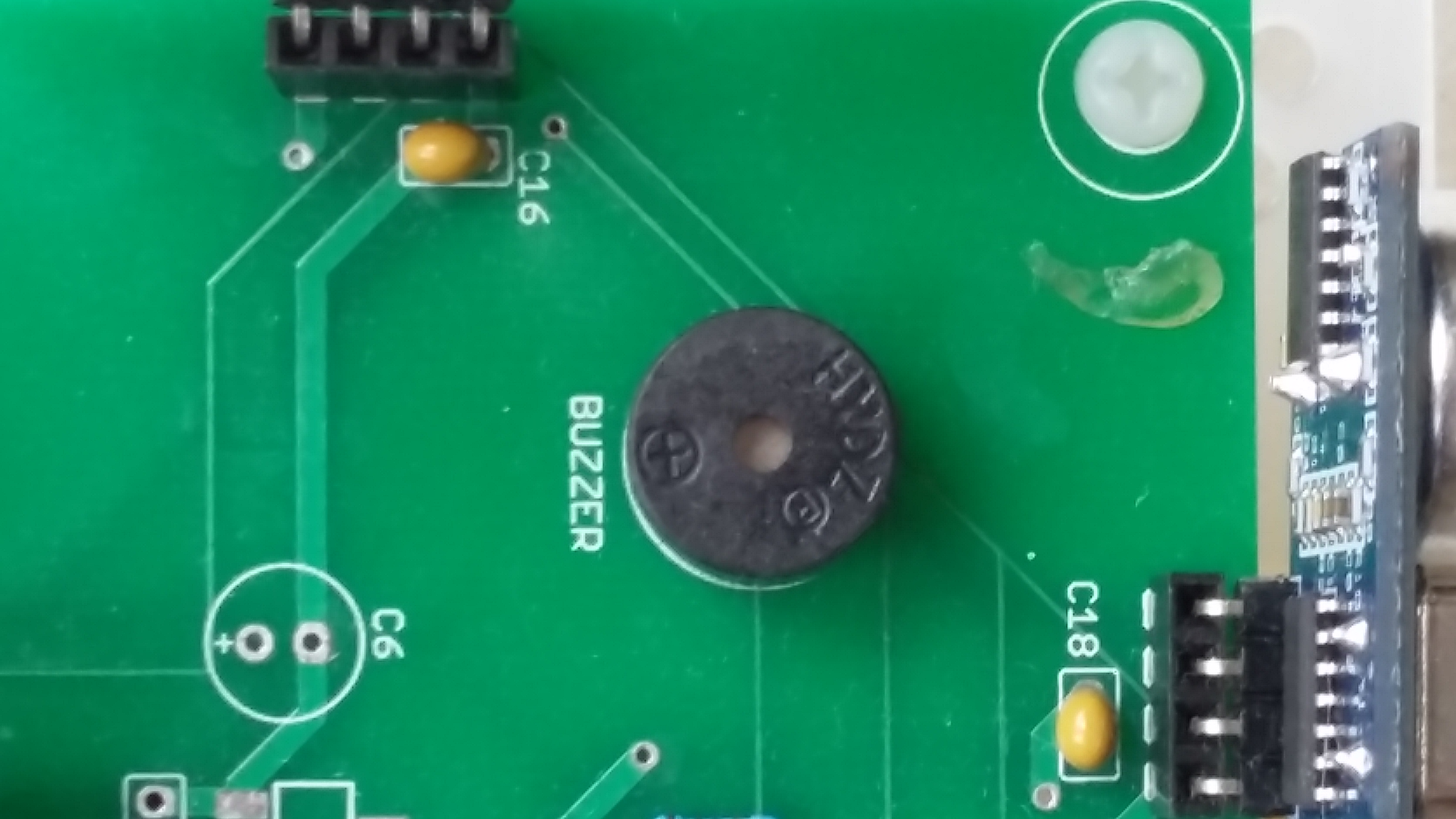
Buzzer
The baseboard contains a buzzer that can generate sound either to draw attention, when it is cornered, or even play rudimentary musical notes. It requires a single pin interface (and a ground). The Arduino library function tone() can be used to generate sound.
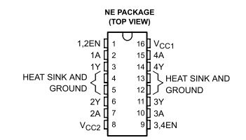
DC Motor Driver – SN754410
Small mobile robots commonly use 4.5 to 6 V dc gearmotors. These motors draw a current well under 1 amp. An H-bridge driver is used to drive the robot dc motor through PWM control available from Arduino Nano. The H-bridge allows the control of not only motor speed but also the motor direction (forward or reverse). As the robot uses 2 motors (left and right), either a motor driver with 2-H-bridges is needed or 2 drivers each with an H-bridge is needed.
The Baseboard contains a socket with to hold SN754410 – Texas Instruments dual H-bridge driver. The driver is available in DIP format and is easily plugged in the 14-pin DIP socket.
Ultrasonic Ranger
Ultrasonic rangers have become standard units on mobile robots for detection of any obstruction in its path. These modules are available with 3-pin, 4-pin, and 5-pin interfaces. The 4-pin module HC-SR04 has become very popular and can be easily sourced.
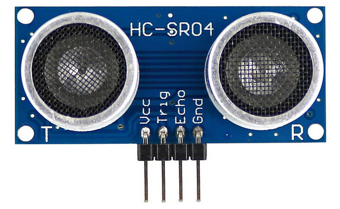
The baseboard contains four 4-pin sockets to allow the direct mounting of 4 HC-SR04 ultrasonic rangers. With 4-sensors the robot can detect obstruction from all four side (including, if some device trying to seek up from behind)
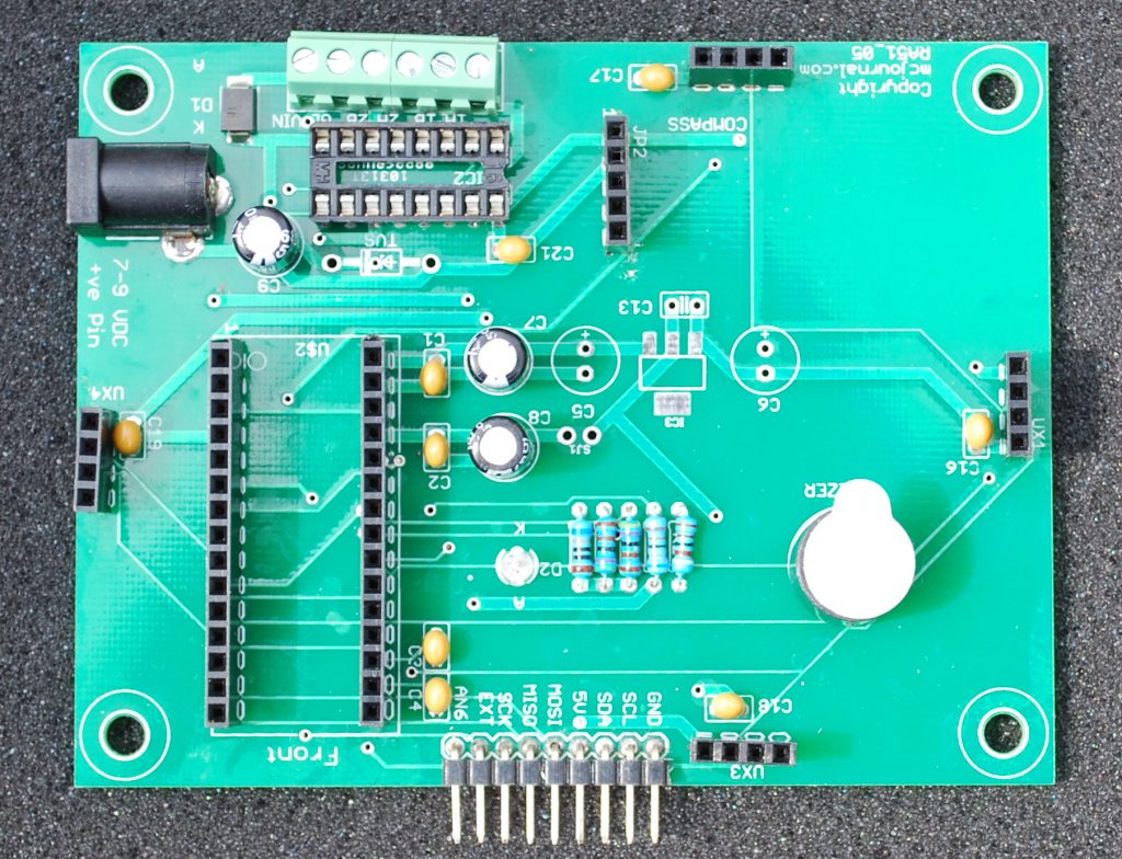
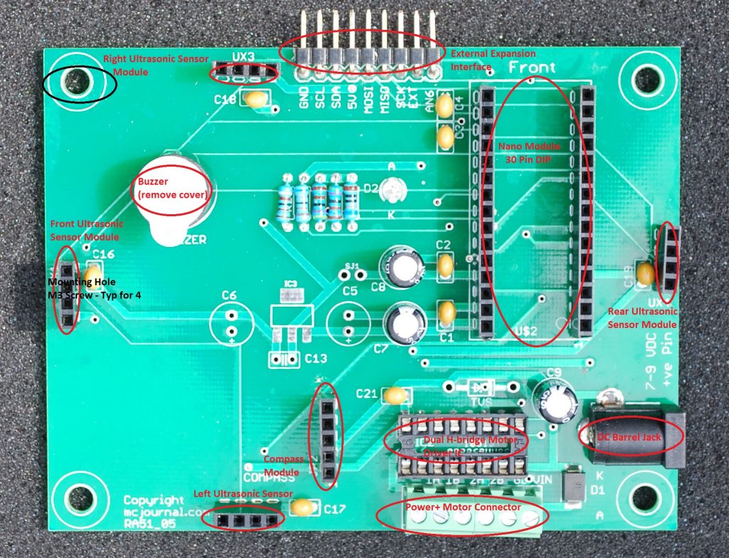
Populating the NanoBot Baseboard
The first step in building the robot is the preparation of the baseboard. As the baseboard comes with socket for mounting components, the installation simply requires the insertion of the modules (with pins) at the indicated locations.
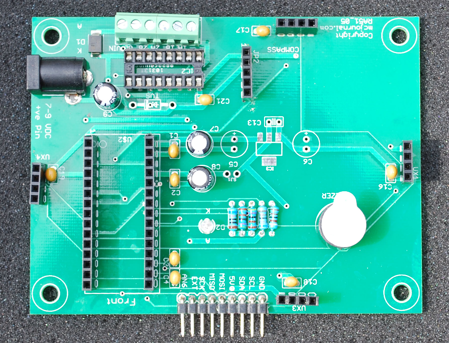
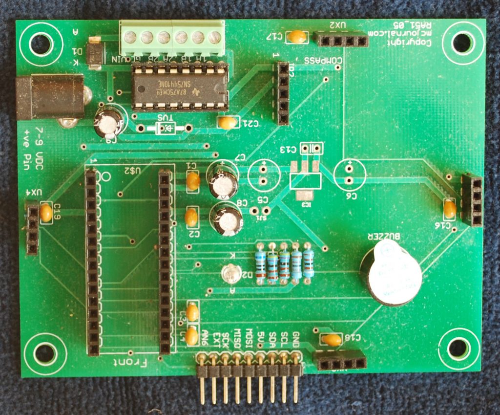
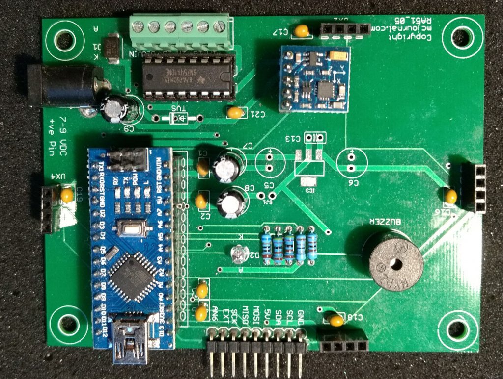
The above marked up image shows the locations of various modules.
The above image shows the dual H-bridge driver SN754410 IC mounted on the baseboard.

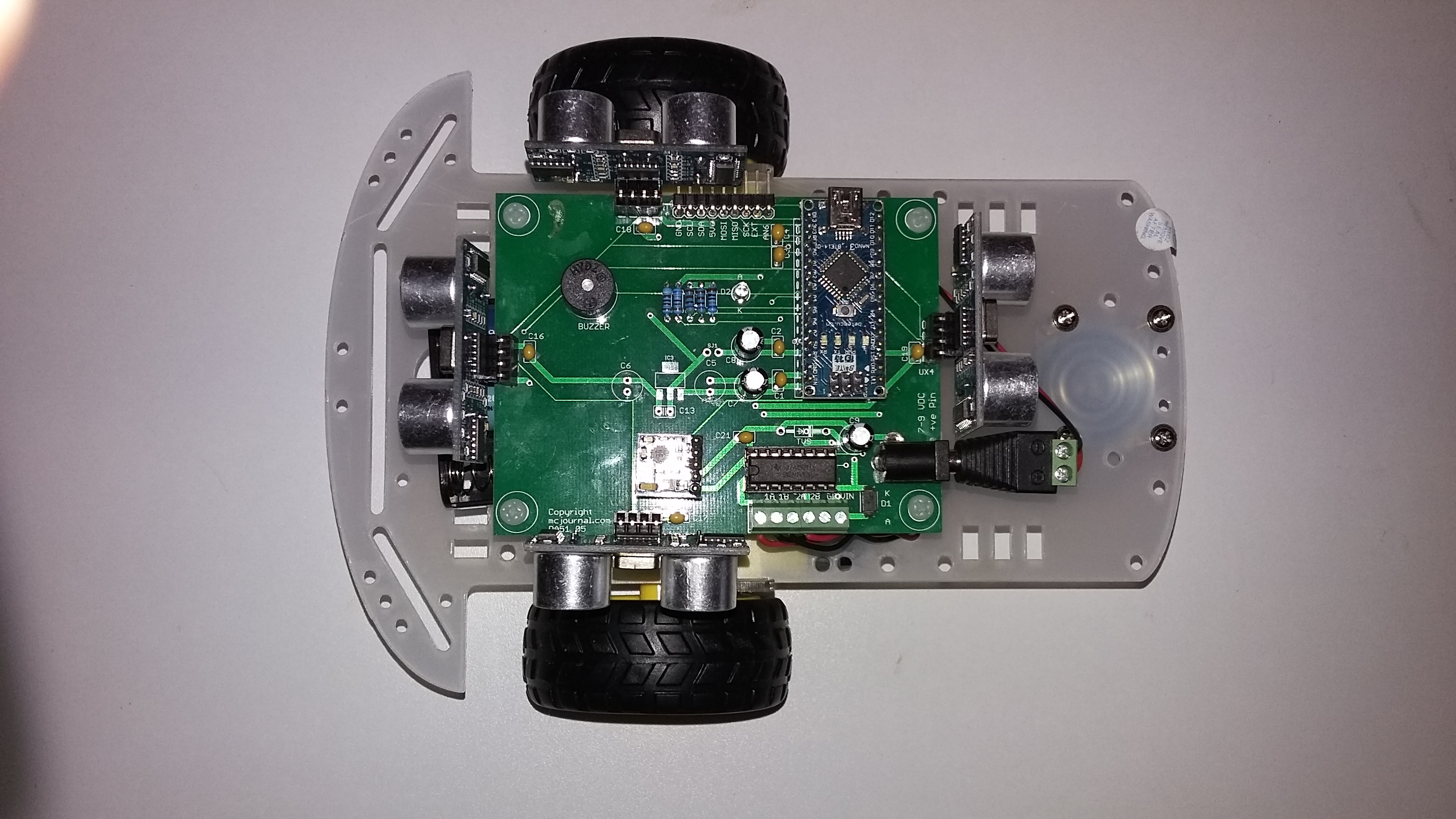
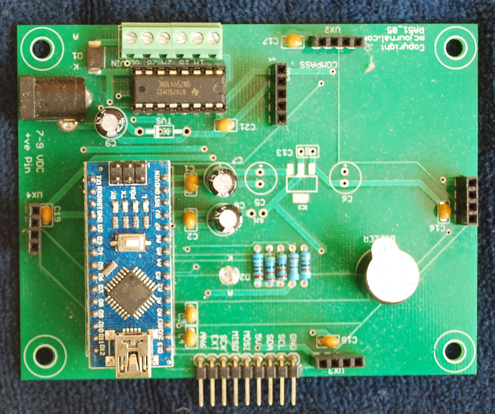
The above image shows the baseboard also populated with Arduino Nano compatible module that has the pins soldered. At this point the robot controller is ready to be programmed using Arduino. It is a good idea to test the unit to ensure that the controller is functional. Although, no physical sensor is yet connected to the nano controller, the buzzer is soldered to the main board and is connected to pin A2. Before testing the sound operation the cover from the buzzer should be removed.
Power jack supplies (7.2 to 9V- power to Arduino Nano and also to the motor driver SN754410 IC. 5V supply to the board (and all its installed modules) is provided by the 5V voltage regulator present on Arduino Nano. The power requirement of all the modules (including the ultrasonic rangers) is fairly low and Arduino Nano can easily supply that current.
Testing the Board – First Step
Before proceeding further, it is a good idea to run a basic test to ensure that it is functioning properly. The basic test will consist of connecting the board to Arduino IDE and run a simple program.
Blinking Test – Hello World
This is a very common and traditional test that will demonstrate the powering of the board and ability to run a small program. The main board contains a power-on LED, which lights up, as soon as the main board is receiving 5V power. The Arduino nano board also contains a power on LED and an additional LED that can be controlled by user program.
User LED is connected to port pin PB5 of Atmega328 ( the microcontroller used in Arduino Nano). In Arduino language, this pin is referred to as ’13’ and serves as a digital pin. The anode of LED is connected to PB5 through a series dropping resistor, while the cathode of the LED is connected to ground.
/*
* Nano_Bot_2
* Dec 3 2017
* Blink test
* The board is powered and tested for power on operation, program downloading and execution
* The LED on digital pin 13 is blinked 0.2 second ON and 1 secondon OFF
* The pin needs to be declared as 13 and not D13
*/

void setup()
{
digitalWrite (13, LOW); // initially set pin low to turn off the LED
pinMode(13, OUTPUT); // set D13 pin as output
}

void loop()
{
digitalWrite(13, HIGH); // turn pin high to turn LED ON
delay (100); // wait for 0.1 s

digitalWrite (13, LOW); // turn pin low to turn LED OFF
delay (1000); // wait for 1 s
}
After the successful test, the remaining modules can be added one by one.
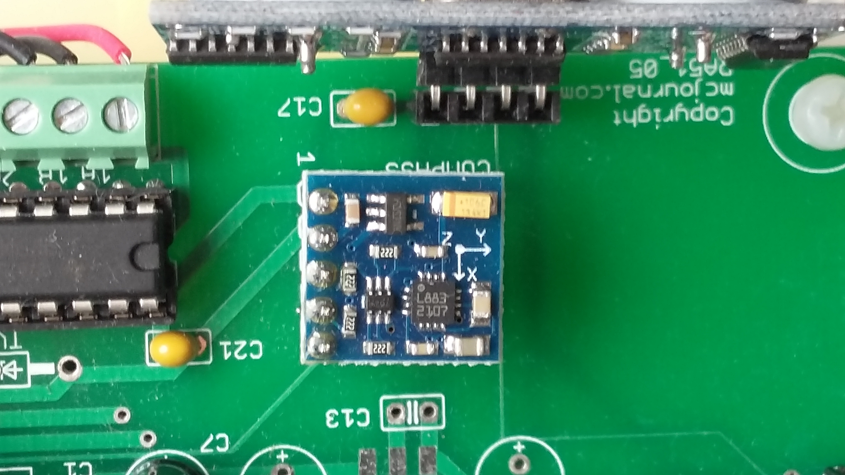
Installing the Compass Module
The compass module is the next module that can now be plugged in. The module has 5 inline pins that are inserted in on-board socket. Take care that it is installed in the correct orientation, pointing away from SN754410 – the motor driver IC (See image below).