PIC16F87X
Bootloader
With
PIC
Flash Module
S Gupta
Introduction
In the past issue, PIC16F873/6 Flash Module was discussed. In this article, a small bootloader program, which can be used to load a user program into Flash Module, is discussed. The bootloader program occupies a small space in PIC16F876 memory space and is initially burned in PIC through a PIC programmer. A PC with uploader software is required to control the transfer of user code into PIC flash memory. There are some slight variations in PIC16F87x processors and this article will focus on 28-pin PIC16F876 uC. Bootloading of other devices in the family can be similarly implemented.
Discussion
There are several issues to be dealt with, whenever
designing a bootloader. It can be made as comprehensive as one can image, with
various check & balance operations. A comprehensive bootloader will require
a sizeable program code memory space and require a longer development cycle. On
the other hand, a minimal bootloader can be implemented, which will simply
accepts a byte of data through serial port and program it into flash memory.
All the intelligence of check and balance operations can then be left to the
program running on a PC. A small bootloader will occupy a much smaller space in
program memory and will pose fewer limitations on final user code. This is the
approach taken here.
Another issue that needs to be dealt with is deciding the
proper method of placing the uC in boot mode. In Motorola’s HC11 family of uCs
a set of mode setting pins are dedicated to this function. On PIC16F87x uC
there is no such facility[i]
and at least one hardware pin will need to be reserved for this operation. This
may not be acceptable in some designs, especially in the existing ones where a
flash PIC16F87X is replacing the non-flash device. Thus continuing with the
spirit of PIC designers and to accommodate the existing designs, the hardware
boot mode will not be implemented and the software boot mode is used here.
Software Boot Mode
Software boot mode can be implemented in one of the
following two ways:
PIC initiating sign on: In the
first case, PIC takes the initiative and sends a control character through
serial port. It waits for a response from a PC running the uploader program. If
an appropriate reply is not received, the query is attempted a couple more
times, before deciding that there is no uploading facility available.
PC initiating sign on: Here PC
initiates the communication and PIC provides a response. If communication is
successfully established, the bootloading can take place.
For a Flash module being programmed on a workbench, there is
no significant difference in either of the two approaches, but if the
bootloading is to be carried on a unit already in field, the first approach may
prove to be risky. When the unit is interfaced to several other devices, an
unwarranted character on serial communication channel is not desirable. It can
happen, whenever PIC uC is reset (say) due to a power outage. On coming out of
reset PIC will try and establish communication through a serial link by
transmitting a character. Thus the second approach, where PC initiates the
communication is more robust.
Bootloader System
The complete bootloader system consist of the following:
·
PIC Flash Module with PIC and serial communication circuit
·
PIC pre-programmed with bootloader code
·
PC running an uploader program.
A PIC programmer is needed to pre-program the PIC with the
bootloader code.
Bootloader Program
The PIC bootloader code can be considerably simplified, if the
entire intelligence (decision making) can be left to the PC uploader program.
The uploader will ensure that bootcode is not overwritten and some of the other
critical memory areas are left untouched. The bootloader program is now limited
to the following tasks:
·
Entering the Bootmode
·
Reading user code through serial port
·
Writing to Flash memory
·
Reading back the programmed user code from Flash memory and
echoing it.
Click
here for assembly language source file
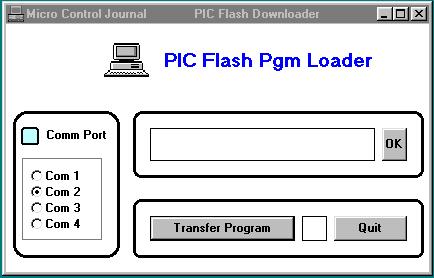
PC Uploader Program
The uploader program running on PC is responsible for
transferring the user code to Flash Module and verifying that code has been
programmed in flash memory. Its major tasks are:
·
Set up the communication port
·
Read the hex file containing user code.
·
Establish communication with Flash Module
·
Transfer program data
·
Read the programmed data from Flash Module and verify
·
Terminate communication.
Entering the Bootmode
When a reset occurs, the program jumps to the bootloader
code located in upper program memory space occupying an address range of 1F00 –
1FFF. On a PIC16F876 this section can be write protected, and thus eliminating
the possibility of overwriting of the bootcode. The code performs the following
tasks:
·
Initialize the serial port (9600 baud)
·
Enters a timed loop (3 sec)
·
Waits for the loop to time out
·
Checks the serial port buffer for a command character (ASCII
02 - STX)
·
If the command character is not received enter another timed
loop
·
If no command received within three attempts, exit the
bootmode
·
On receipt of the command character, send acknowledgement
(ASCII 06 - ACK)
Bootmode Operation
Once a command is received and PIC enters the bootmode, it
enters an infinite loop for accepting data from PC and executing the
programming task. The exit from this state can only occur after a reset has
been initiated. All communication is in ASCII format.
·
Receive a colon character (:) from PC and echo it back
·
Receive two characters representing the number of bytes in
this line and echo each character back to PC, as it is received
·
Receive four characters representing the program memory
address and echo each character back to PC, as it is received
·
Receive two characters representing the program data byte
and echo each character back to PC, as it is received
·
Program the data byte
·
Read the data byte just programmed
·
Echo the data byte as two characters (PC can verify the
data)
·
Send a control character (ASCII 04 - EOT), once all data
bytes in this line of code are programmed
·
Repeat the steps (wait for a colon character from PC)
A loss of communication from PC, while the boot loading is
taking place will effectively hang up the PIC. The only recourse, in this case
is to eliminate the cause of interruption and restart the process.
PIC Flash Module
A PIC module containing PIC16F876 Flash microcontroller is available
from Forth Microsystems
contact forthmicro@mcjournal.com