Serial Communications Systems
in
the Automobile
Ross Bannatyne
Transportation Systems Group, Motorola Inc.
Introduction
The last few years has seen the electronic content in the automobile increase significantly. Driving this growth is consumer demand for enhanced safety features, entertainment systems, added convenience functions and government edicts on emissions controls. In order to cope with the vastly increased electronic content, there are several changes which are happening in the vehicle. The conventional power supply, a 12 volt battery, will be replaced in the near future with a more powerful source. More attention is being focused on failsafe and fault-tolerant systems design. In addition, the vehicles electronic systems architecture is transforming into a network of real-time distributed control systems.
The Motivation to Network
The main motivation behind networking the vehicle was to address the increases in cost and weight that the addition of many electronic systems brings. Each system typically included their own wiring harness which connected up the ECU, battery, instrumentation panel controls, sensors and actuators. The wiring consisted of separate copper wires which added a significant amount of weight to the vehicle. Before the introduction of multiplexed networks, a luxury vehicle could include over 1 mile length of insulated wiring consisting of around 1500 individual wires and over 2000 terminals . As well as being expensive and heavy, it was becoming impossible to even feed the large wiring harness into the door.
The conventional wiring system was also a source of many reliability issues. As with all electronic systems, the more interconnections which were present, the more opportunities there were for mechanical interfacing problems. It was no surprise that many field failures were the result of such interconnect issues.
The solution to the problem was to replace all the individual wiring systems, where possible, with a multiplexed serial communications network. Theoretically, a single bus system which linked up all the related systems in the vehicle. This would reduce number of wiring harnesses, weight, cost, assembly time, and would promote better reliability through reduced number of interconnections. A simplified diagram is shown in Figure 1 which compares a door control system using a conventionally wired means and a multiplexed wiring system. The door shown on the left hand side of the illustration uses many more wires to connect up the functions door controls and must be fed through the door. The door shown on the right hand side of the illustration uses a multiplexed wiring system which is connected to the controller in the instrumentation system. The multiplexed wiring system uses considerably fewer wires and connections.
Vehicle network messages are transmitted as serial packets of information. Usually they consist of three fields - a ‘header’, the destination address for the packet, ‘data’, usually three to twelve bytes in length, and ‘error correction’, a cyclic redundancy code or checksum to ensure that the packet has not been corrupted.
Electronic Control Units (ECUs) have been steadily increasing within the vehicle for a number of years. Powertrain controllers, Anti-lock Braking System (ABS) controllers, Airbag controllers and controls for Body electronics functions such as window lifters and electronic locks are probably the most common examples. Conventionally, these systems have been self-contained and did not interact with each other by sharing information. Recently however, it has been recognized that the exchange of data between different automotive systems can enhance overall vehicle functionality quite significantly.
A simple example of the enhanced functionality which can result from networking systems is traction control. Traction control systems optimize the grip which a tire has on the road surface when the vehicle is accelerating. This function requires modulation of brakes and must also interact with the powertrain system in order to retard engine torque. This function can be realized relatively easily through a simple serial communications link between the ABS ECU and the Powertrain ECU. A multiplexed wiring system is used.
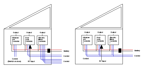
Figure 1 - Reduction in wires required for multiplexed door controls
Another example of sharing information between vehicular systems using the multiplexed bus system is for a ‘brake booster’ system. This system will apply extra braking force if it is determined that the brake pedal is depressed very rapidly (as is the case in a panic braking maneuver). As the pedal travel sensor is normally connected to the Powertrain ECU, this information is available to the ABS ECU via the link between the Powertrain ECU and the ABS ECU.
Similarly, the ABS ECU can send information on vehicle speed to the navigation system. This is used as a ‘sanity check’ against the information which is acquired from the Global Positioning System (GPS). There are many such instances when the availability of a data communications network between vehicular systems allow much more complex hybrid systems to be realized.
The network can also be used to improve the diagnostic capability of the vehicle. Rather than having to locate a fault by debugging many different systems, a networked vehicle will usually have one port (often under the dashboard) to which diagnostic equipment can be connected. As each of the electronic systems are networked together, this port allows access to all the electronic systems in the automobile. Faults or status information can be acquired much more easily than examining several different independent systems.
Different Types of Network
Unfortunately connecting together all of the modules in the vehicle is not as straightforward as linking them all to a single network. Usually there are several networks which each have characteristics tailored towards the requirements of the types of control systems which are included. The Society of Automotive Engineers have defined three classes of vehicle serial communications networks; Class A, Class B and Class C. Figure 2 details main features of these three networks.
Feature Class A Class B Class C
Speed 1 kb/s 40 kb/s 1 Mb/s
Latency <50 ms <20 ms <5 ms
Oscillator % tol. 20 2 0.01
Transmission Single wire Single wire Twisted pair
Twisted pair Shielded
Coaxial
Fiber optic
Message Priority Yes Yes Yes
Fault-tolerance No No Yes
Figure 2 - Typical Characteristics of Serial Communications Classes
Class A networks are used for lower speed control systems in the vehicle such as body electronics systems. Class B networks is intended as a superset of Class A which runs at a higher speed. Real-time control systems such as powertrain, ABS and airbag systems usually communicate on a Class B network. Class C is an emerging class of networks which will require support for fault-tolerance for safety critical systems. Although Class C networks have yet to be adopted widely, they will be required in future ‘By-wire’ applications for steering and braking.
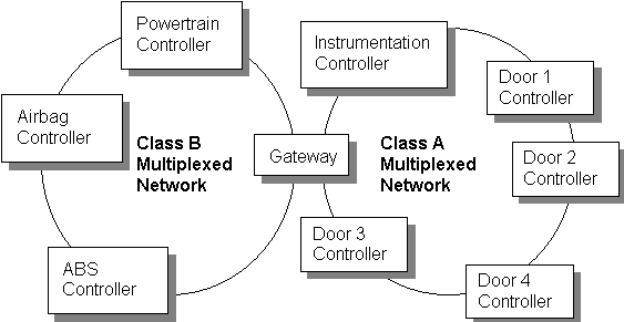
Figure 3 - Typical Multiplexing system in today’s automobile.
Most new vehicles produced today have a Class A and Class B network. This is shown in Figure 3. The networks are linked together with a gateway. The gateway allows information from the high speed real-time network to be shared with the body electronics network. This is useful as, for example, information from the powertrain controller could be used for the tachometer which is controlled by the Instrumentation controller. Each vehicle type will have the same network principle but may have slightly different modules connected to the network.
In the very near future, further systems will be added to the vehicle. Although it would be possible to use the same network for many of the new functions, it would not be practical. The additional performance and complexities which are associated with the higher classes of networks are more expensive to implement than the simple Class A networks. It is also more prudent from a safety standpoint to keep non-safety-critical information apart from the networks which support safety critical systems. Already some luxury vehicles have networks which resemble that shown in Figure 4.
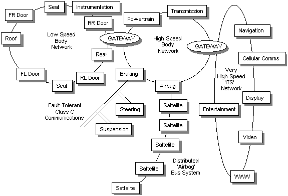
Figure 4 - Advanced Vehicle Multiplexing Requirements
There are five networks shown in Figure 4. The Class A and Class B networks for vehicle control and body electronics control are still there. In addition, certain specialist networks have been added. The Braking, Steering and Suspension controllers are becoming more complex and interactive in order to support full vehicle stability management systems. These systems are linked on a Class C bus which supports fault-tolerance. There is a redundant bus which operates in parallel so that in the event of a fault on one bus, another exists. The Airbag system is composed of many different airbags including side airbags, rear seat airbags, etc. These are all linked on a custom network which is very robust. Finally, a very high speed ‘Intelligent Transportation Systems’ (ITS) network has been added which would use a transmission medium such as fiber optics to transfer audio and video information. Each bus system caters for the characteristics of the system and balances performance with the cost of implementing each network.
There are several multiplexing serial communications protocols which are commonly used. Figure 5 outlines the most popular ones. The Controller Area Network (CAN) was created in the mid 1980’s by auto component manufacturer Robert Bosch GmbH. It has since been adopted by many leading car makers around the world. Current models from Mercedes, BMW and Volvo, among others, already use many CAN nodes in the vehicle. The J1850 protocol has different variations which are favored by different automobile manufacturers. J1850 is currently a more popular solution to vehicle multiplexing in the United States and has not been adopted elsewhere in the world. TTP/C (Time Triggered Protocol / Class C) was developed originally at the Technical University of Vienna. It is currently the leading solution for Class C networks for future systems. Unlike CAN and J1850, TTP/C is based on a TDMA (Time Division Multiple Access) scheme. Instead of messages being event-triggered where a message is sent in response to an event happening, TTP/C is time-triggered. Each message has its own time slot to send state messages, regardless of events. This ensures deterministic transmission of messages.
CAN 2.0B J1850 (PWM) J1850 (VPWM) TTP/C
Class Class B Class B Class B Class C
Affiliation Bosch Ford Chrysler / GM Tech. Uni. of Vienna
Speed 1 Mb/s 41.6 kb/s 10.4 kb/s 1 Mb/s
Bus length Typ. >40m 40m 40m Typ. 20m
Access type Event Event Event Time-triggered
No. of nodes Typ. >16 Not spec. Not spec. Not spec.
Figure 5 - Serial Communication Protocols
Future Trends - Fault Tolerant Networking
Although the electronics industry is by no means short of serial communications protocols, until now there has been surprisingly little progress in developing a low cost network which provides fault tolerant communication. Fault tolerant systems are set to become a growth area in the not too distant future, particularly in the automotive world, as brake-by-wire and steer-by-wire systems are set to become a reality in the next few years.
Such systems must be ‘fail-operational’ as they are deemed safety critical; if the system develops a fault, it could have life-endangering consequences. ‘By-wire’ systems transfer electrical signals down a wire instead of using a medium such as hydraulic fluid to transfer muscular energy. A conventional Antilock Braking System (ABS) is considered ‘fail-silent’; if a fault in the electronic control system is detected, the control system is switched off, leaving the manual hydraulic back-up still operational. If no such hydraulic back-up is available (as in the case of a ‘by-wire’ system), the system must continue to function in the event of a fault occurring.
The unsuitability of the existing communications protocols is mainly due to the fact that they are ‘event-triggered’. A precise moment in time when a message will be received is not specified. A communications protocol can only be predictable if worst case transmission time and jitter are known at the time of the design and meet the requirements of the application. The time delay between presenting a message to be transmitted at the senders interface and receiving the message at the receivers interface is known as the transmission time. Jitter is defined as the variability of this transmission time (maximum transmission time - minimum transmission time).The maximum jitter depends on the longest message that it is possible to transmit. Real-time control applications are very sensitive to jitter and it is an important parameter for developing real-time distributed systems.
A TTP/C based network is shown in Figure 6. Four host controllers are shown. These hosts could be, for example, electronic control units in a vehicle network such as Braking Controller, Steering Controller, Suspension Controller and Powertrain Controller. Each of the four nodes are composed of a Host, CNI (Controller Network Interface) and the TTP/C controller. There are two buses to support redundancy; if a fault develops on one bus, the alternative bus is available.
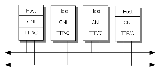
Figure 6 - Typical TTP/C based system
The host controller of each module runs the application software. The sending of messages is controlled by a scheduling table called the Message Descriptor List. This list contains the information which controls access to the bus at any particular time. The communications system and TTP/C controller will operate autonomously from the host software, using the Message Descriptor List which is stored in the CNI. Each node in the network is synchronized to a common global time. The Controller Network Interface (CNI) decouples the communication network from the host and provides a data sharing interface between the host and the TTP/C controller. This is best physically implemented with dual port RAM that can be addressed by either the host or the TTP/C controller.
The third segment of the node is the actual TTP/C controller which connects the node to the network. The TTP/C controller provides guaranteed transmission times with minimal latency jitter, fault-tolerant clock synchronization and fast error detection. In support of fault tolerance, the TTP/C protocol also supports replica determinism (replicated nodes with identical behavior) as well as a replicated communications channel.
The system is based on state message transmission; state messages can typically be observed over a longer period of time than an event message which would change every time there is a new event, as opposed to periodically. State messages are well suited to closed loop control type applications where inputs are required to sampled usually once per control cycle. There is no queuing of messages in the CNI as a new version of the state message overwrites the old one every control cycle.
Replica determinism is implemented by duplicating nodes so that if one node develops a fault, the signal from the node is replaced by a replica node which broadcasts the same information in a different time slot. The main strategy for fault tolerance in the TTP/C system is fail-silence. A fail-silent architecture must deliver a correct output or no output at all. When no output is generated, the hardware has developed a fault. A number of error detection strategies, both in hardware and software, must be employed in order to ensure fail-silence. The TTP/C controller uses watchdogs as well as a bus guardian which enable the bus driver only during the nodes transmission time and disables it at all other times. This prevents the babbling idiot problem which can cause havoc in priority based event triggered systems.
The TTP/C protocol has been adopted by many major automobile manufacturers and module suppliers in order to facilitate the highly dependable networks which will be required very soon on vehicles.